Recently I was commissioned to create motion graphics for Northwest Childrens Theater to be used in a production of Rapunzel. The set features a large projection screen for scene-setting rather than having physical set pieces (the play is a pop-rock musical and most of the set resembles a stadium concert stage). Among the challenges of creating dynamic animated content, a major aspect of the show is to display Rapunzel's hair as it's deployed from the tower window. http://vimeo.com/35366140
The script calls for the hair to be let out and pulled back up many times so I didn't want to use a single animation as it would become quite repetitive after seeing it for the second or third time. Like the rest of the motion content in the play I decided it'd have to be a dynamic system rather than a pre-rendered video. Using processing, I hacked out several tests before I had what I wanted. Once I was happy with the motion I integrated the resulting code into the larger eclipse project that I had been working on for the rest of the performance. Here's a little review of where I started and the progression from concept to final implementation.
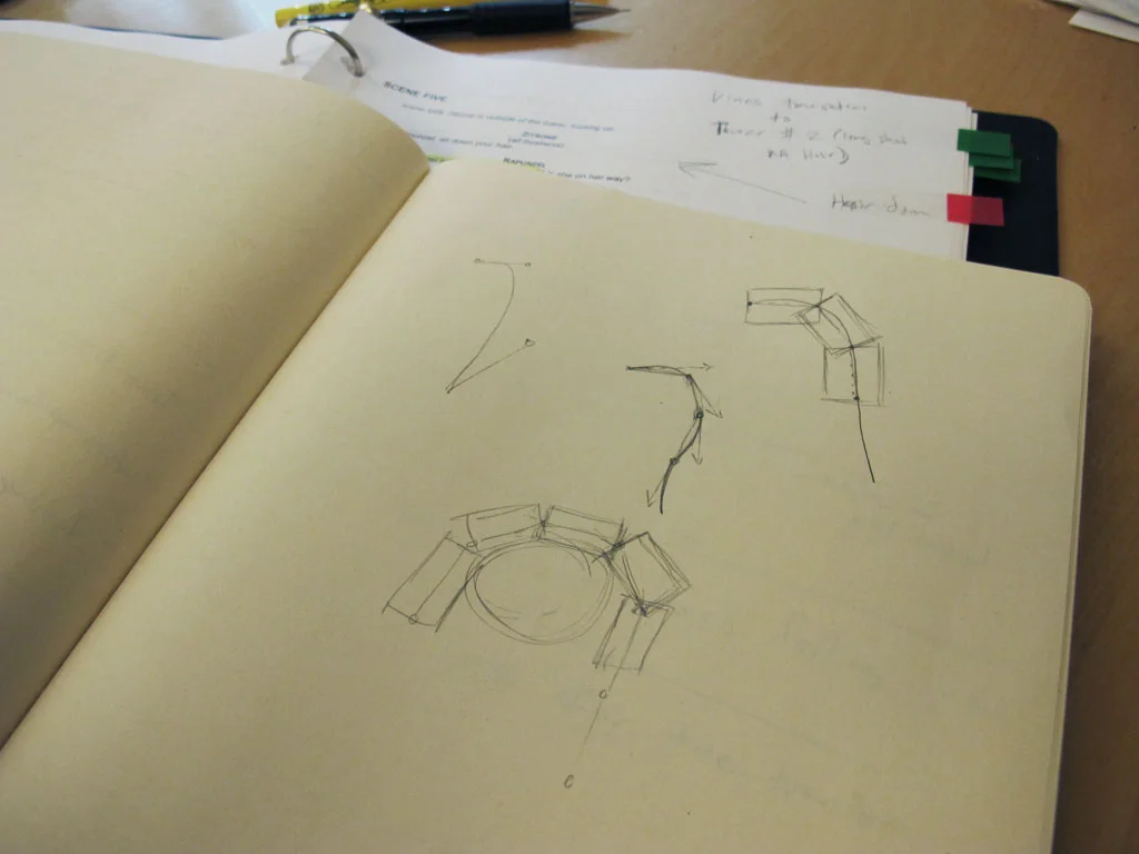
Before writing code I spent a few minutes drawing out what I was aiming for. My rough idea was to position a bunch of image segments along a bezier curve. By adjusting the offset of each segment along the curve I could then animate the hair to make it look like it was being lowered from the window.
Planning!
Before writing code I spent a few minutes drawing out what I was aiming for. My rough idea was to position a bunch of image segments along a bezier curve. By adjusting the offset of each segment along the curve I could then animate the hair to make it look like it was being lowered from the window.
Test 1 : Segmented bezier spline
The first test was to get a series of connected nodes moving along a bezier spline. This would later become the basis for drawing a series of hair segments aligned along the path.

Test 2: Images aligned along a bezier spline
Next, I added some code to draw images at each point in the segmented path. The angle of each image is calculated via atan2 using the coordinates of the target point and the neighboring point. The results worked well but started to look funny when the curve was more extreme since the joints between each image became very obvious.

Test 3: Drawing a single textured mesh
The previous technique worked when motionless but when animated it looked sort of like links in a chain rather than a contiguous braid of hair. I also wanted to be able to use a single image of hair rather than ask the illustrator, Caitlin Hamilton, to draw a bunch of individual segments. This turned out to be easier than I thought since I already had the code done to figure out the angles of each segment. Vertices are positioned perpendicularly on each side of a segment and the mesh is drawn from end to end as a single quad strip.
At this point I felt like I was getting close to finished, but the motion of the hair really didn't feel right. I added some random movement to the bezier control points so the hair would appear to sway, but the extending motion along the path had an unnatural and sort of creepy look to it. This lead to something I thought of in my initial brain storming, but had dismissed as overkill.

Test 4: Verlet physics simulation!
The last test was more of a complete re-do than an iterative development. Rather than use a bezier curve, I decided to go for an actual physics simulation of linked nodes. Thanks to toxiclibs this was a fairly simple task, and fortunately I was able to use a bunch of the existing code to calculate segment angles and build the textured mesh for rendering. As soon as I saw it in motion it was obviously the superior solution.
This final test worked great and I quickly set about integrating it into the performance tool. The deploy/retract animation is achieved by raising and lowering the top end point of the verlet particle string. There are also some invisible constraints which guide the particles making it look like they’re moving out and over the window sill (shown as red shapes in the above screen shots). It sure seemed like overkill when I though of this but I’m really glad I gave it a try. The results are exactly what I was shooting for in the beginning, and after lots of testing I’m fairly sure the physics won’t glitch out and ruin the show.