projecting onto mirror arrays

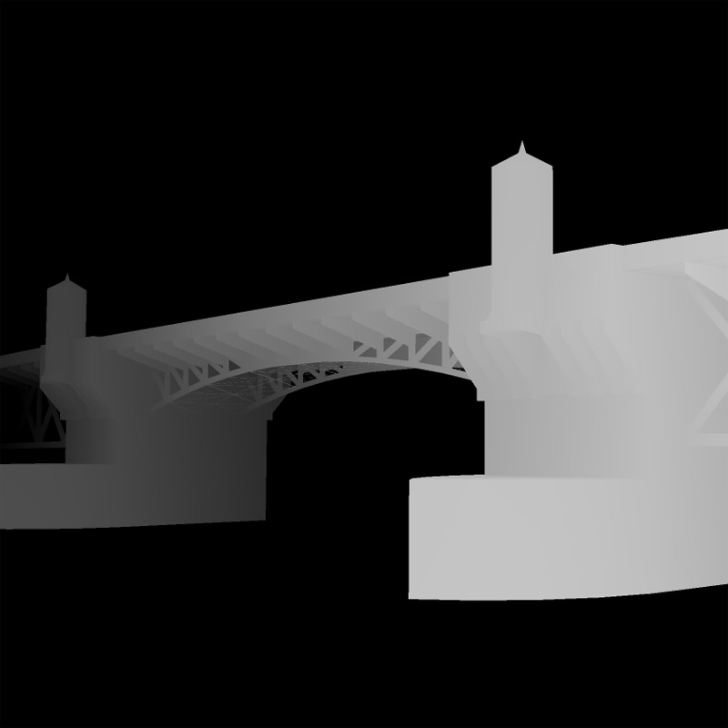
This March I was fortunate enough to be invited to participate in a three night event put on by Liminal as part of the March Music Moderne event in Portland.  In addition to providing projection mapping for "Capital Capitals," I worked with Bryan Markovitz to create an installation piece based on Gertrude Stein's novel "The Making of Americans." 

The installation included some custom software that I wrote which would drive projected content.  This content would be projected onto several large pieces of art hanging from the walls of the room.  This all seemed straight forward until we saw the room..  It was approximately the size of a shoe box, meaning my projector would only yield about a four foot wide image.  This gave us very little flexibility for placement of the artwork since all the projected content would end up being constrained to a very small portion of the space.  I was not happy about this.

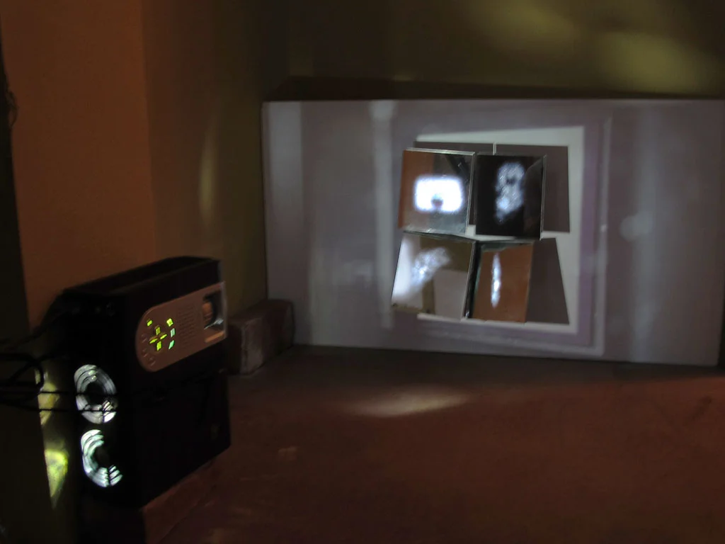
The most obvious solution I could think of was to use a single large mirror to increase the throw distance.  After testing this idea it only added a marginal increase to the projection size, and due to the already limited space the physical setup was quite bulky. The idea of using a mirror stuck with me though.  If a single mirror works, why not use several small mirror panels, each one aimed at a different location in the room?  Thus was born the idea of an adjustable mirror array.

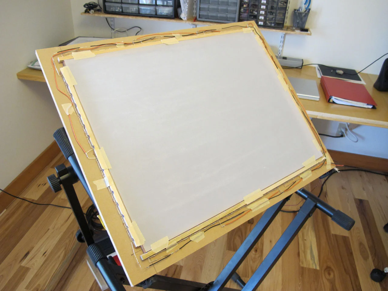
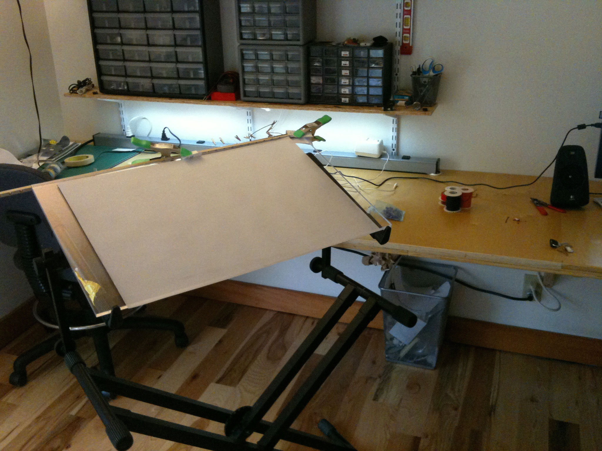
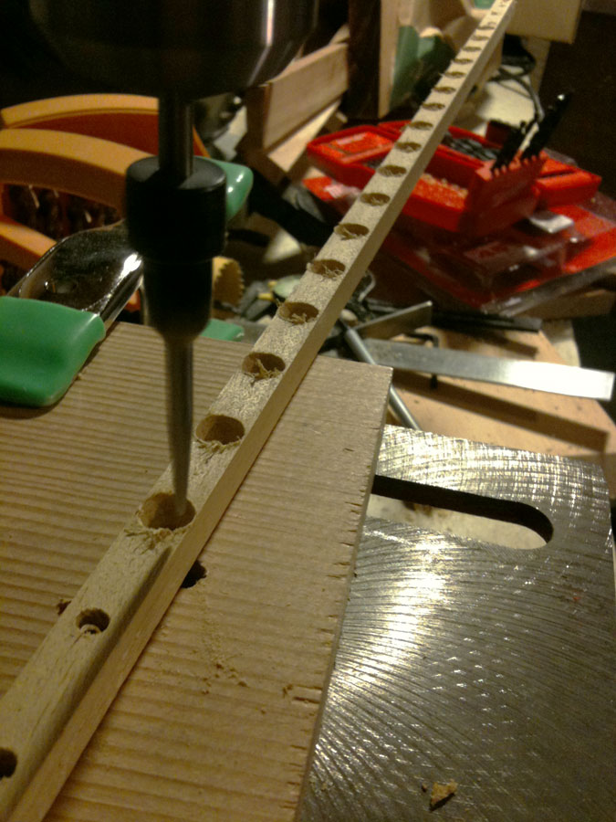
First I tested out the concept at home with a couple of mirrors, and once I was convinced that my projection mapping software worked through a mirror I set about building the adjustable mirror array.  The array is a set of four small (about 5" square) mirror panels mounted on brackets I made that allow the mirror to swivel horizontally or vertically.  The biggest downfall of this system is trying to drag the control points around when all the mouse movements are reversed.

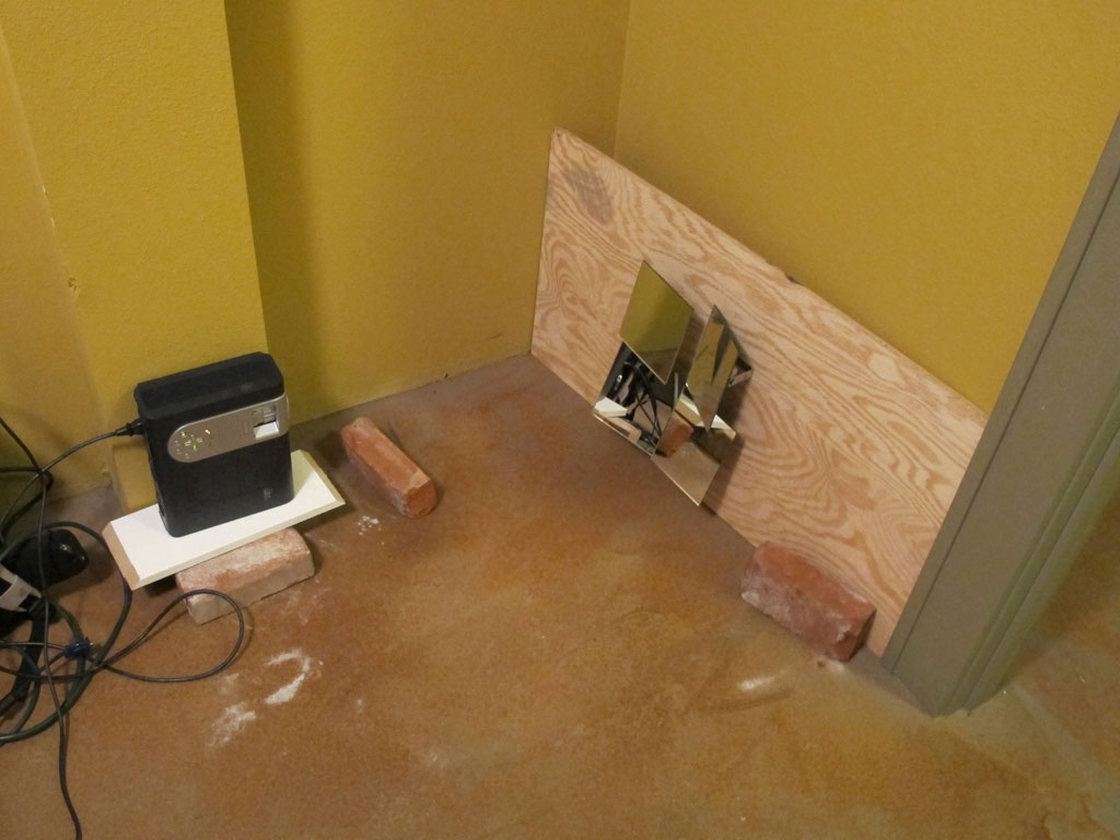
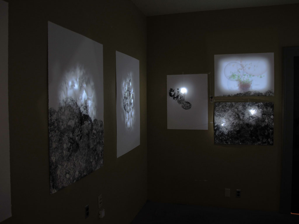
The final installation included four projected regions spanning three walls of the small room with an almost 180 degree spread around the space.  Being able to project at such strange and diverse angles created a very nice effect since it removed the projector from the experience.  In most cases, it's simple to visually track back from the wall and notice the source of the projection, but when the projector is tucked over in the lower corner of the room the projected regions seem to float on the walls as if by magic.

Rapunzel, Rapunzel, let down your.. verlet physics simulation?

Recently I was commissioned to create motion graphics for Northwest Childrens Theater to be used in a production of Rapunzel. The set features a large projection screen for scene-setting rather than having physical set pieces (the play is a pop-rock musical and most of the set resembles a stadium concert stage). Among the challenges of creating dynamic animated content, a major aspect of the show is to display Rapunzel's hair as it's deployed from the tower window. http://vimeo.com/35366140

The script calls for the hair to be let out and pulled back up many times so I didn't want to use a single animation as it would become quite repetitive after seeing it for the second or third time. Like the rest of the motion content in the play I decided it'd have to be a dynamic system rather than a pre-rendered video.  Using processing, I hacked out several tests before I had what I wanted.  Once I was happy with the motion I integrated the resulting code into the larger eclipse project that I had been working on for the rest of the performance.  Here's a little review of where I started and the progression from concept to final implementation.

Before writing code I spent a few minutes drawing out what I was aiming for.  My rough idea was to position a bunch of image segments along a bezier curve.  By adjusting the offset of each segment along the curve I could then animate the hair to make it look like it was being lowered from the window.

Planning!

Before writing code I spent a few minutes drawing out what I was aiming for. My rough idea was to position a bunch of image segments along a bezier curve. By adjusting the offset of each segment along the curve I could then animate the hair to make it look like it was being lowered from the window.

Test 1 : Segmented bezier spline

The first test was to get a series of connected nodes moving along a bezier spline. This would later become the basis for drawing a series of hair segments aligned along the path.

Test 2: Images aligned along a bezier spline

Next, I added some code to draw images at each point in the segmented path. The angle of each image is calculated via atan2 using the coordinates of the target point and the neighboring point. The results worked well but started to look funny when the curve was more extreme since the joints between each image became very obvious.

Test 3: Drawing a single textured mesh

The previous technique worked when motionless but when animated it looked sort of like links in a chain rather than a contiguous braid of hair. I also wanted to be able to use a single image of hair rather than ask the illustrator, Caitlin Hamilton, to draw a bunch of individual segments. This turned out to be easier than I thought since I already had the code done to figure out the angles of each segment. Vertices are positioned perpendicularly on each side of a segment and the mesh is drawn from end to end as a single quad strip.

At this point I felt like I was getting close to finished, but the motion of the hair really didn't feel right. I added some random movement to the bezier control points so the hair would appear to sway, but the extending motion along the path had an unnatural and sort of creepy look to it. This lead to something I thought of in my initial brain storming, but had dismissed as overkill.

Test 4: Verlet physics simulation!

The last test was more of a complete re-do than an iterative development. Rather than use a bezier curve, I decided to go for an actual physics simulation of linked nodes. Thanks to toxiclibs this was a fairly simple task, and fortunately I was able to use a bunch of the existing code to calculate segment angles and build the textured mesh for rendering. As soon as I saw it in motion it was obviously the superior solution.

This final test worked great and I quickly set about integrating it into the performance tool. The deploy/retract animation is achieved by raising and lowering the top end point of the verlet particle string. There are also some invisible constraints which guide the particles making it look like they’re moving out and over the window sill (shown as red shapes in the above screen shots). It sure seemed like overkill when I though of this but I’m really glad I gave it a try. The results are exactly what I was shooting for in the beginning, and after lots of testing I’m fairly sure the physics won’t glitch out and ruin the show.  

multi-touch projection table

A few weeks ago I spent some time building an FTIR multi-touch table.  I thought I'd post some pictures to share how it turned out and mention a few of the things I learned along the way.  It's still definitely a work in progress but I wanted to document it before I forget the details.  My motivation for doing this was to have access to a large scale multi-touch interface for design and prototyping purposes.  Plus it's fun to play with and I like to build stuff.

For this screen I decided to go with the FTIR method since it's compact and I think it will allow for some interesting physical configurations that other methods, not being as self-contained, wouldn't support.  It also seemed like a reasonably simple project and had low material costs which were both important factors as this would be simply used for prototyping things in my home workshop.

Here's how it turned out:

As far as materials go, I got a chunk of 3/8" thick cast acrylic from TAP plastics, a sheet of velum, ~100 infrared LEDs, a tube of clear silicone sealant and a PlayStation 3 USB camera.  Those items along with miscellaneous wood bits and some wire were all I needed for the project.

Things I Learned

Nothing about the project was terribly difficult, but there were some stumbling points that I could have avoided if I had known a few key things.  Maybe they will help you too!

Thing 1 - Acrylic Edges

The edge finish of the acrylic makes a big difference, the clearer the better.  Rough saw cut edges scatter the IR light and will really dim the touch points.  I used varying grits of sandpaper down to about 350, then I buffed it with a polishing wheel.  You'll want to end up with an edge you can see through like glass, and should look sort of like a "hall of mirrors" effect when you peer into it edge-wise.  It's hard to take a photo of this effect, but the following picture should illustrate what I mean.

Thing 2 - Visible Light Filter

From my initial readings online I tried using a piece of the film from an old floppy disc.  This works to reduce visible light, but also blocks significant amounts of the IR which makes the touch points very dim.  I tried a piece of exposed film negative which made a dramatic difference.  There's more visible light getting through but the signal to noise ratio is really good and I'm getting excellent tracking now.

Thing 3 - Camera Position

Even though CCV has calibration for the camera, it doesn't seem to handle keystone distortion well at all.  I was unable to get good registration if the PS3 camera wasn't lined up very precisely with the screen.  I find it hard to imagine that I'm the only one who had trouble with this, maybe I'm just doing something wrong in CCV?  Anyhow, it was frustrating enough that I made my own calibration utility that sits as a shim between CCV and my own projects, correcting the TUIO coordinates on the fly.

slicing things up

I've been playing with this idea for a while and finally spent a few grueling hours with an exact-o knife in order to knock out a little proof of concept before I spend the time and money having a bunch of material cut out via CNC or something.  This process involves sampling "slices" of a depth map at fixed intervals and using each slice to create a vector profile.  The resulting output is a set of long vector shapes that collectively approximate the original model and can be rendered in any size and from any material (well, any flat material).

This set of images shows the initial depth map, an example of the vector output from my processing sketch, and a paper prototype.

The first few paper prototypes look good and I'm confident this process will scale up very well.  Imagine a 20 foot wide 3d wall-scape made from stained birch plywood strips, connected vertically by steel rod.  If you're looking for some stunning artwork for your home or business then look no further!

This whole idea started with a topological map of mount St. Helens I found online.  Soon after that I started looking for methods of generating depth maps so I could use any arbitrary 3d geometry.  As luck would have it, rather than having to familiarize myself Blender I found a tutorial video for faking depth of field in SketchUp which works great as a way of creating depth maps.

projection mapping - augmenting detailed surfaces

After tackling projection onto rectangular surfaces, the next step in this process has been to register a projection with a complex surface.  In this test, I used a letter press print by Colleen Romike.  The print is a pangram and contains many highly detailed shapes which provided a nice test for this process. 

I took a single hand-held reference photo without paying much attention to the lighting, then did a bit of processing in photoshop to create a mask of the letters.  The rest of the registration is taken care of by my projection mapping code and some simple behavioral logic to illuminate the individual letters.

poster mask

The result was actually much better than I was expecting.  With more attention paid to the reference photos, this process should be able to yield stunning results with very little time and effort.