in which I go insane, make quarter scale NES cartridges by hand

I've recently been playing with a local band called Emulator.  We do covers of old Nintendo game music and I play the projector (meaning I do all the projected video effects).  The music is great, and I get to try out all sorts of fun projection mapping ideas.  There will probably be a blog post about that at some point so stay tuned..

In any case, I had this idea to create little Nintendo cartridge key chains to give away or sell at shows. The project went through several different iterations, and ended up becoming quite the elaborate.  It went a little something like this...

Prototyping!

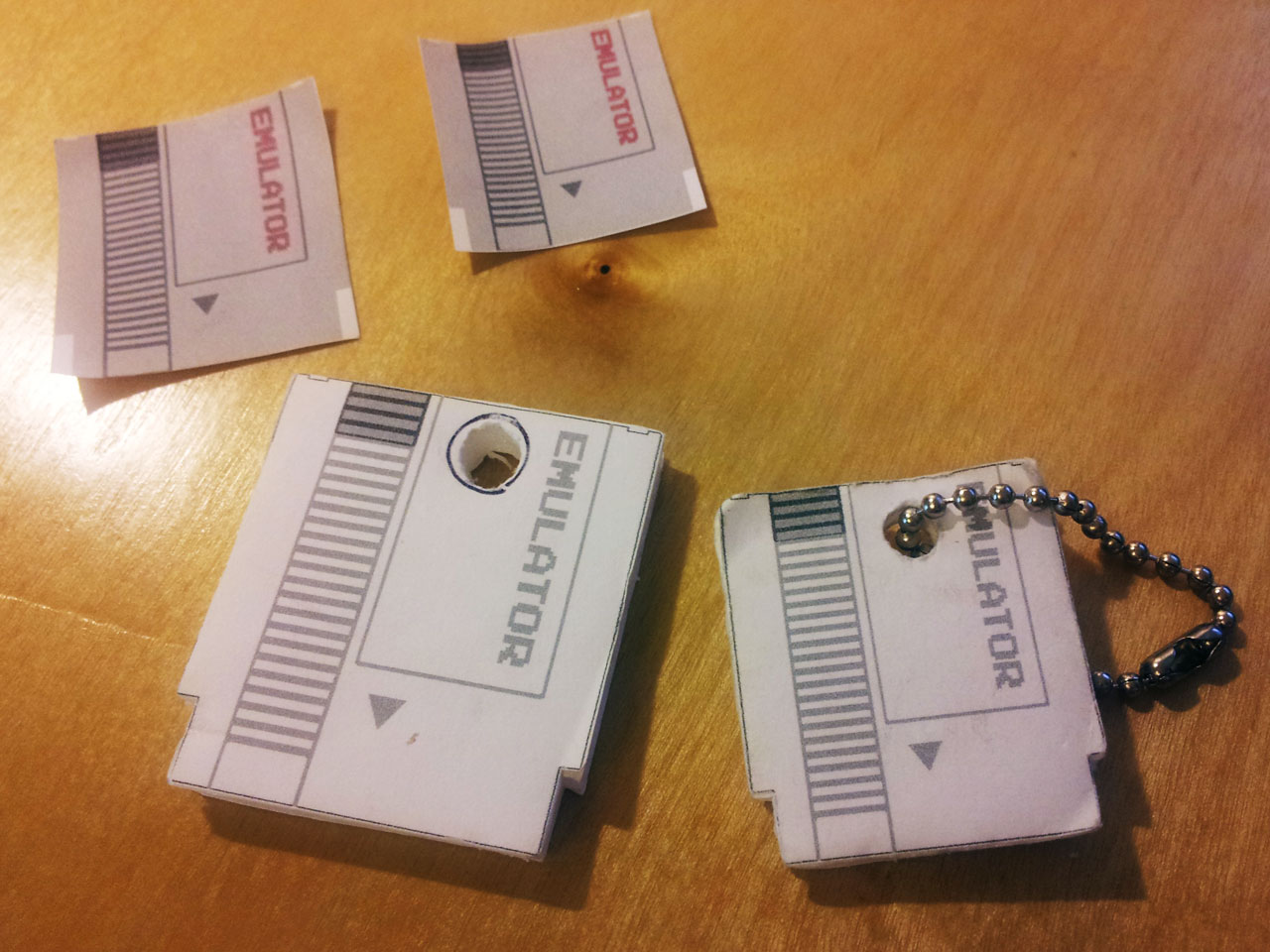
Before getting into the actual manufacturing, I figured I should know what I needed to make.  I started by measuring and mocking up a cross section of a nintendo cartridge in Illustrator, and printing it out in a few different sizes.  After that I used the printed images as a template and cut foam core pieces to use as mock ups.  I put them on a chain and carried them around on my keys for a few days to see how the different sizes felt in my pocket and on my keychain.  This was very valuable because I was leaning towards the larger size until I found it to be bulky and awkward.

Manufacturing

First idea, LASERS!

Back when I was playing with Son of Rust, I made a bunch of laser cut keychains that looked sort of like those translucent chips they're always fiddling with to reconfigure the ship computer in Star Trek the Next Generation.  I figured I could do something similar with opaque gray plexiglass and it'd look something like a NES cartridge.  This ended up being a bust because I couldn't find gray plexiglass, and after looking into it the price to make each keychain was just a little too high to make sense.

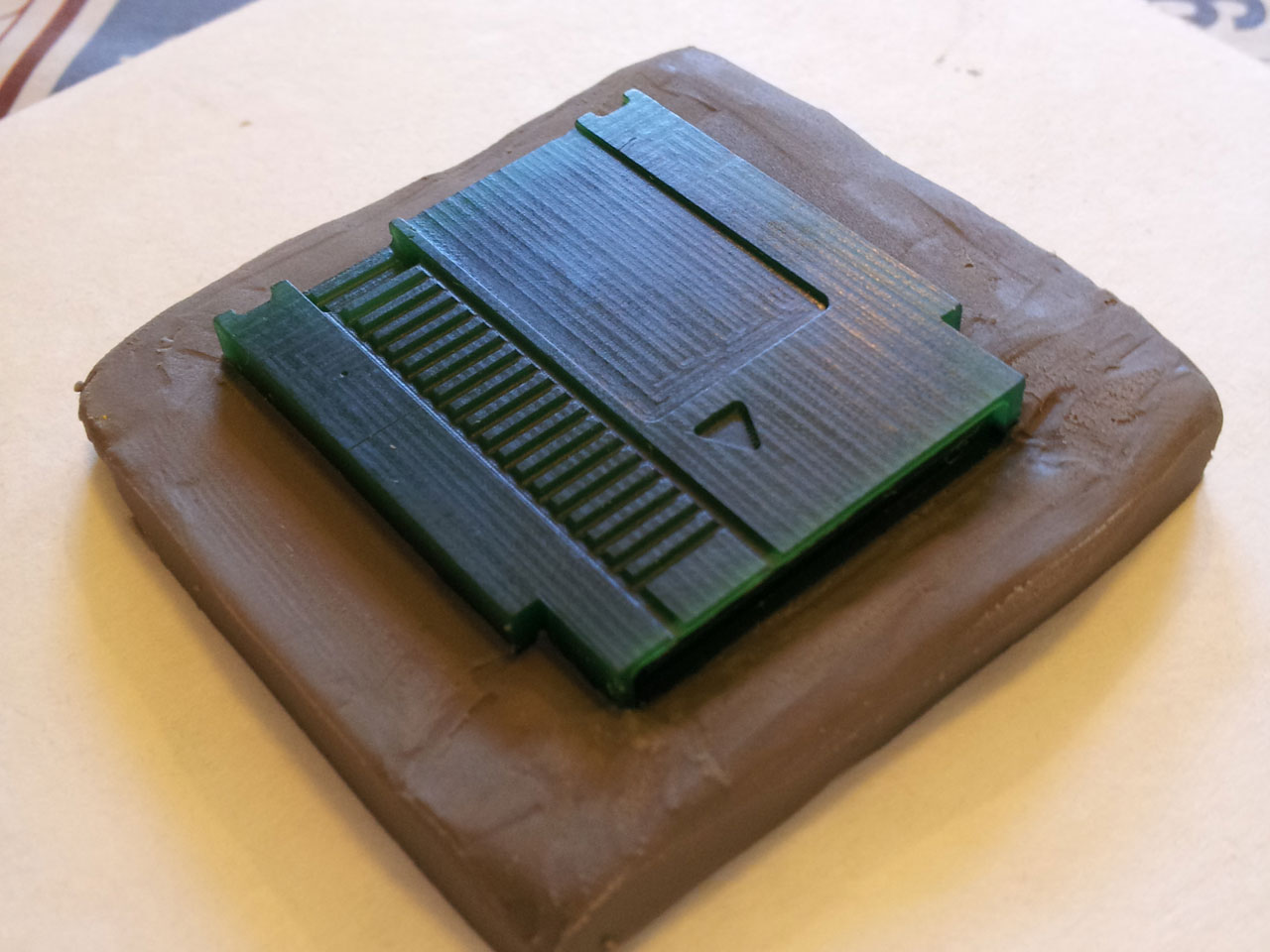
Second idea, 3D PRINTERS!

This seemed like a viable solution, but the output of extruded 3d printers still has a pronounced grain from the plastic filament.  This can be solved by tooling the finished piece but would mean a lot of manual labor for each part.  Since I don't have a 3d printer yet, I'd have to have that work done by someone else so the cost was again an issue.

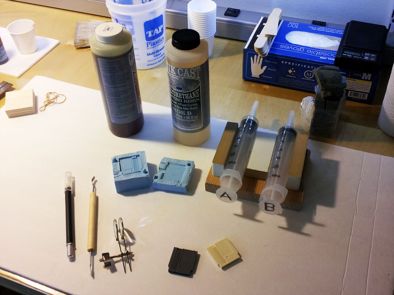
Final idea, resin casting!

Casting copies of a tiny cartridge using a silicone mold and some polyurethane resin seemed like a good solution, the cost was unbeatable (only about 15 cents worth of resin per part).  However, I'd never done any casting or mold making before and I still needed a master model to create the mold.

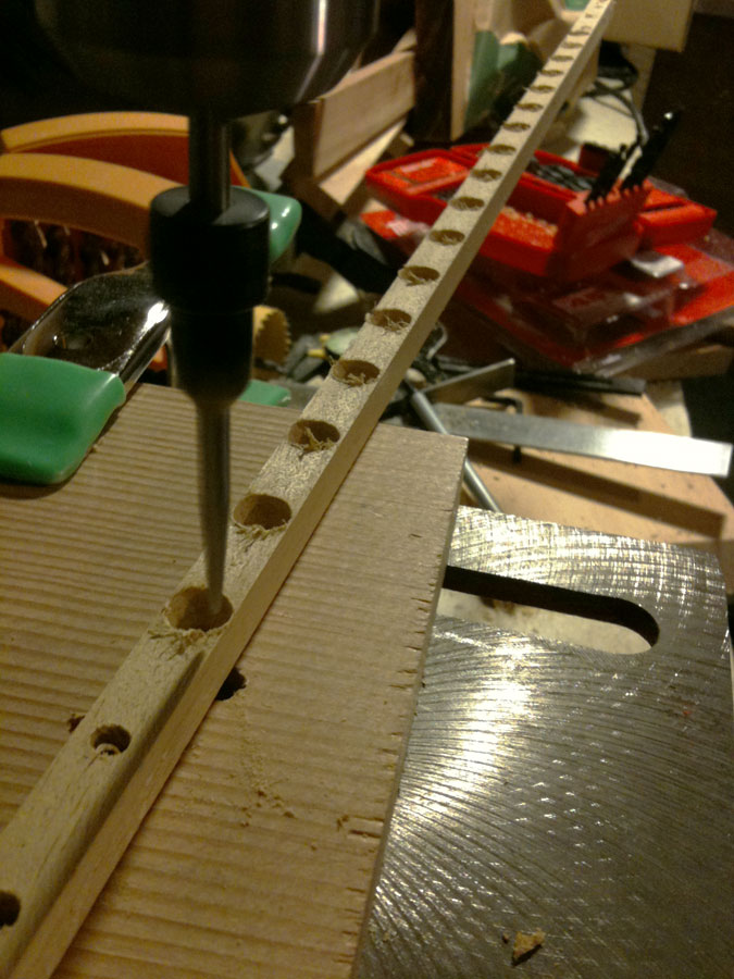
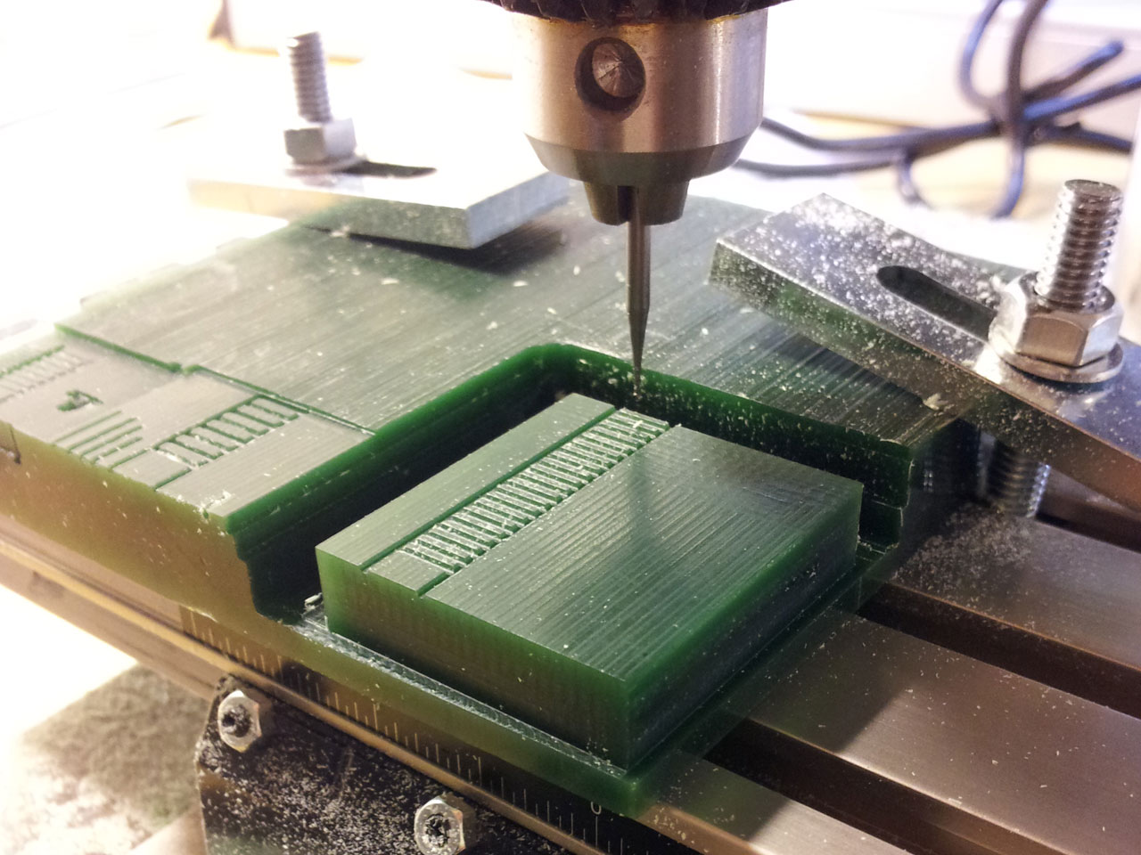
Rather than order a 3d printed model, I took on the task of manually milling one from jewelers wax using a miniature drill press and X/Y stage.  This was done entirely by hand and I now have a huge appreciation for CNC machines..  I used a 0.05 inch dremel cutting bit, and a 0.025 inch engraving bit and manually milled off the wax using the X/Y stage in multiple passes like an etch-a-sketch.  I spent some time with my dial calipers and a full scale cartridge to keep the proportions right, but most of it was done ad-hoc.

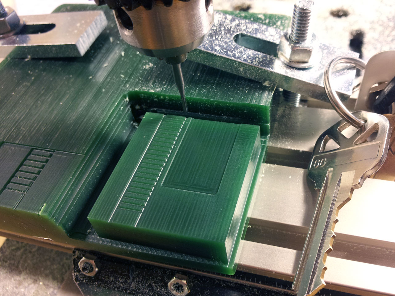
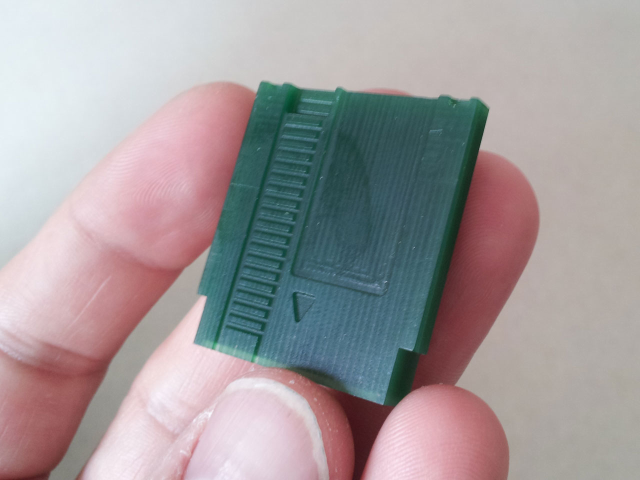
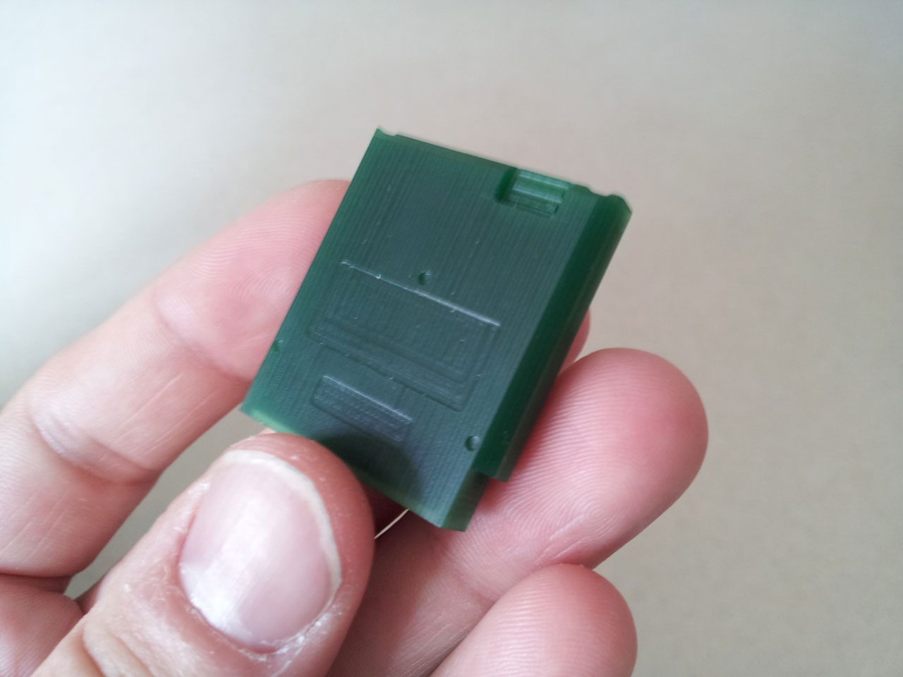
Originally I was just going to add the major physical features but once I had a few of the small details added I realized I had to go all the way so I put the recessed areas in the back, screw holes, and even the little grip marks on the sides.  I'm glad I went to the trouble because they came out looking great.

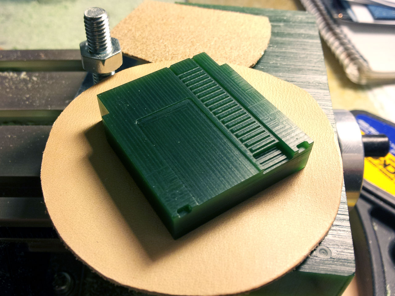
After I had the wax model finished, I was ready to make a mold. The first couple of molds worked ok but it became clear that some of the physical parts of the model were too thin and didn't cast well.  Also the tooling marks on the cartridge were quite pronounced which I didn't like.  I sanded off the tooling marks, and made a couple additional molds which are now operating like a tiny factory in my work shop.
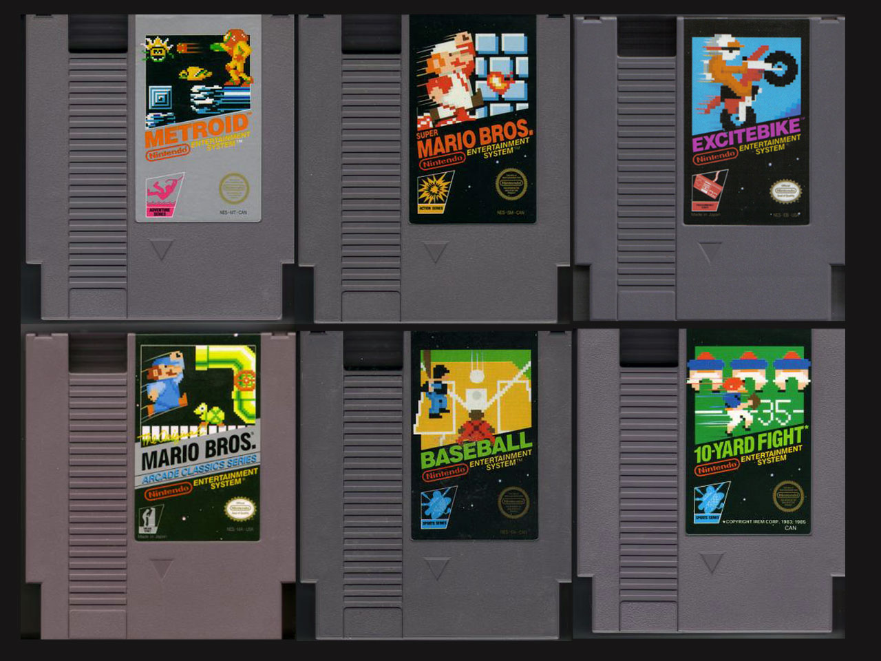

Labels

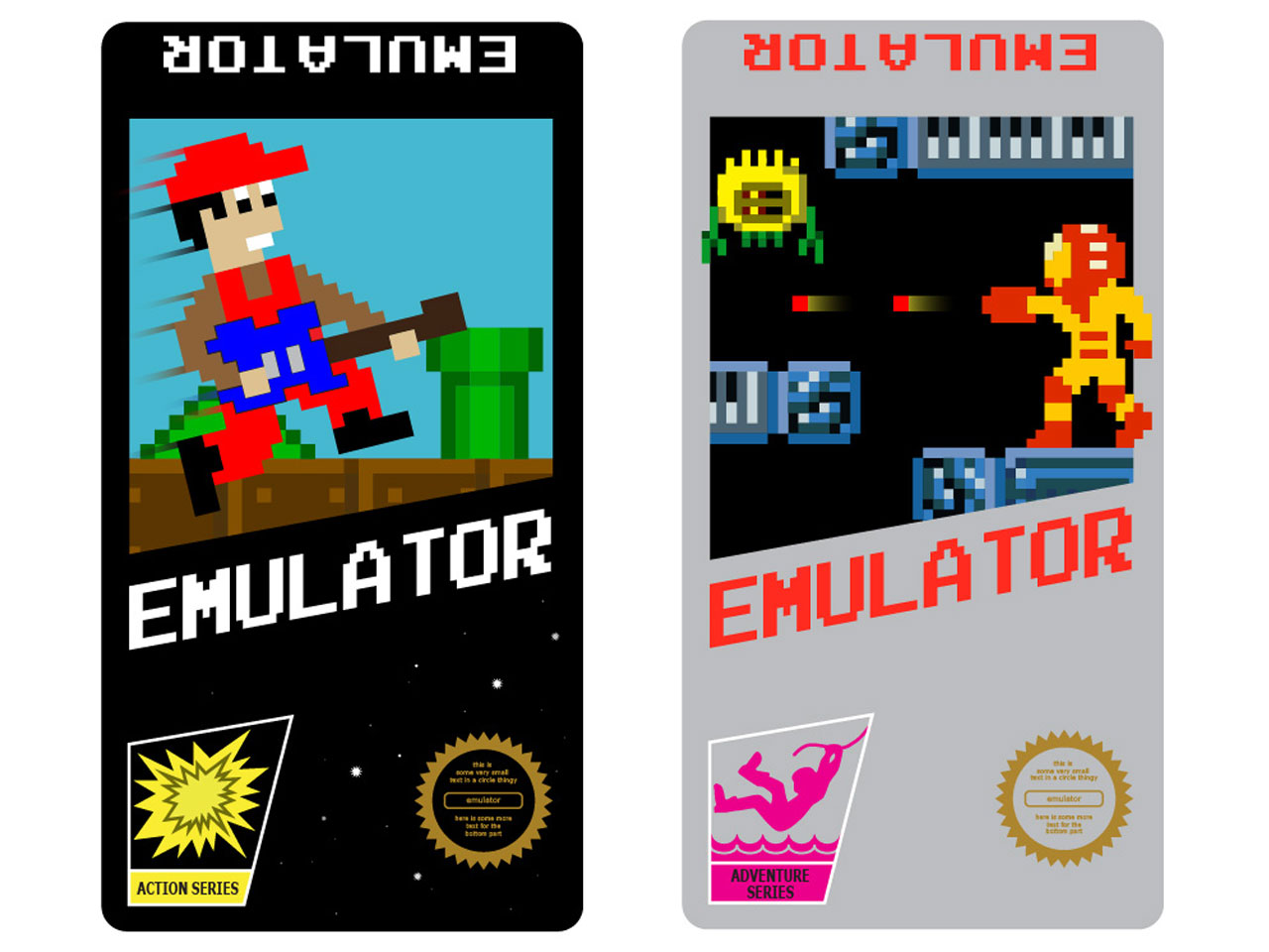
You can't just have a blank cartridge.. How would you know what game it is!?  In the interest of keeping things authentic, I studied the label designs of a hand full of classic games.  There are a lot of games released early in the platform's life that have very consistent label design, so I used that design aesthetic as a guideline.

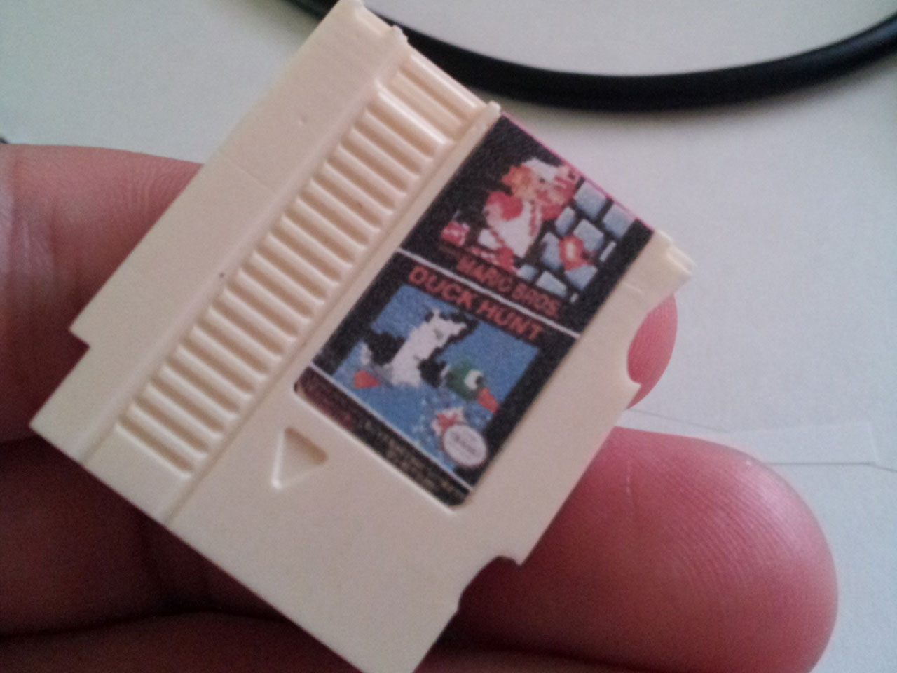
Borrowing the design language of those original cartridges I came up with two custom label designs with musical themed artwork. No Limits PDX were able to print my designs and cut the 0.025 inch radius into the corners.  They have a fancy printer that can both print and cut on adhesive backed vinyl stock.  They were able to get nice full bleed prints with a very precise edge.
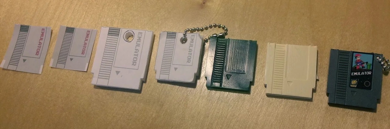
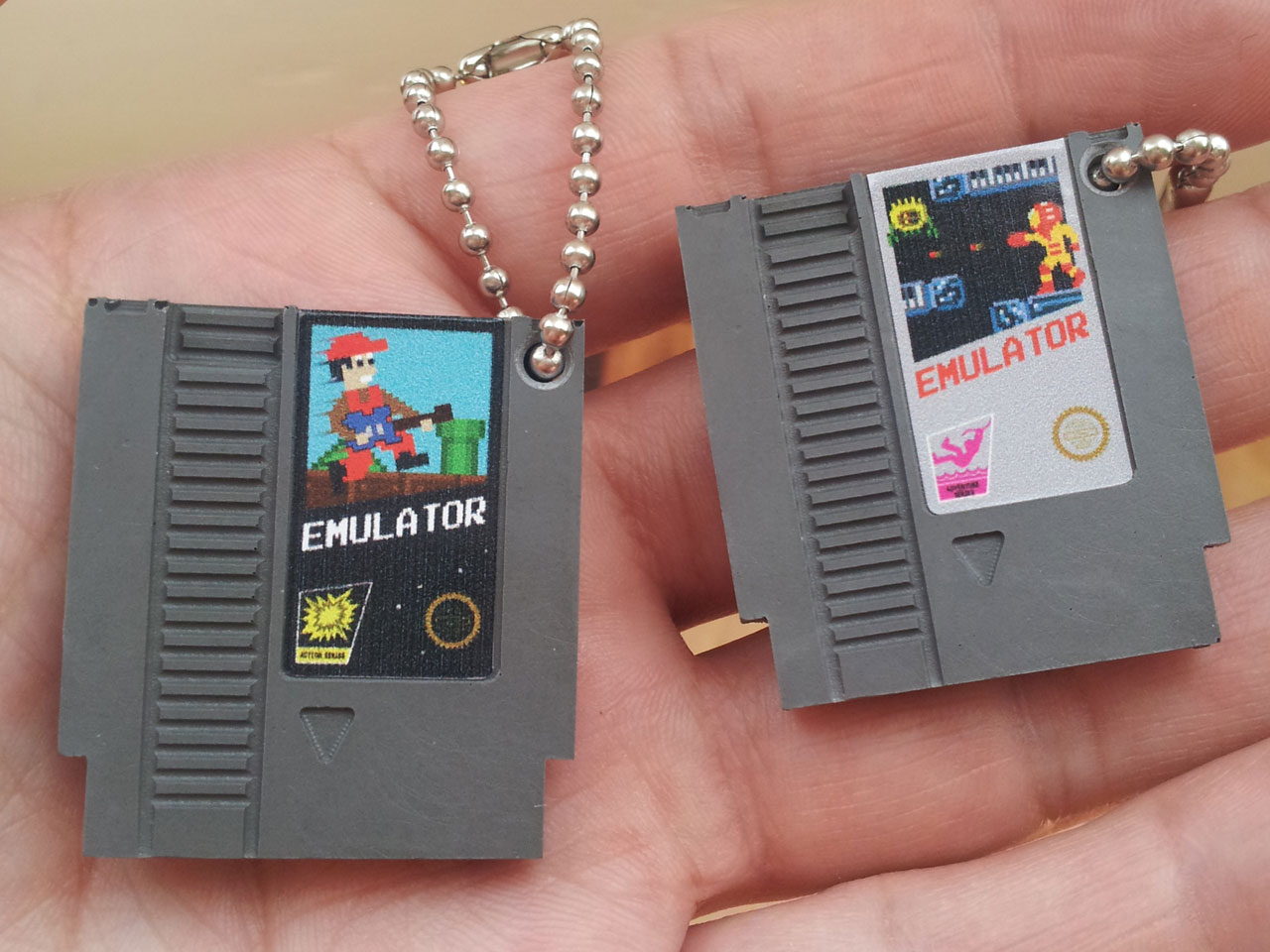
Finished!

So, here they are.  Many hours of work and lots of learning went into this project and it turned out way better than I was expecting.

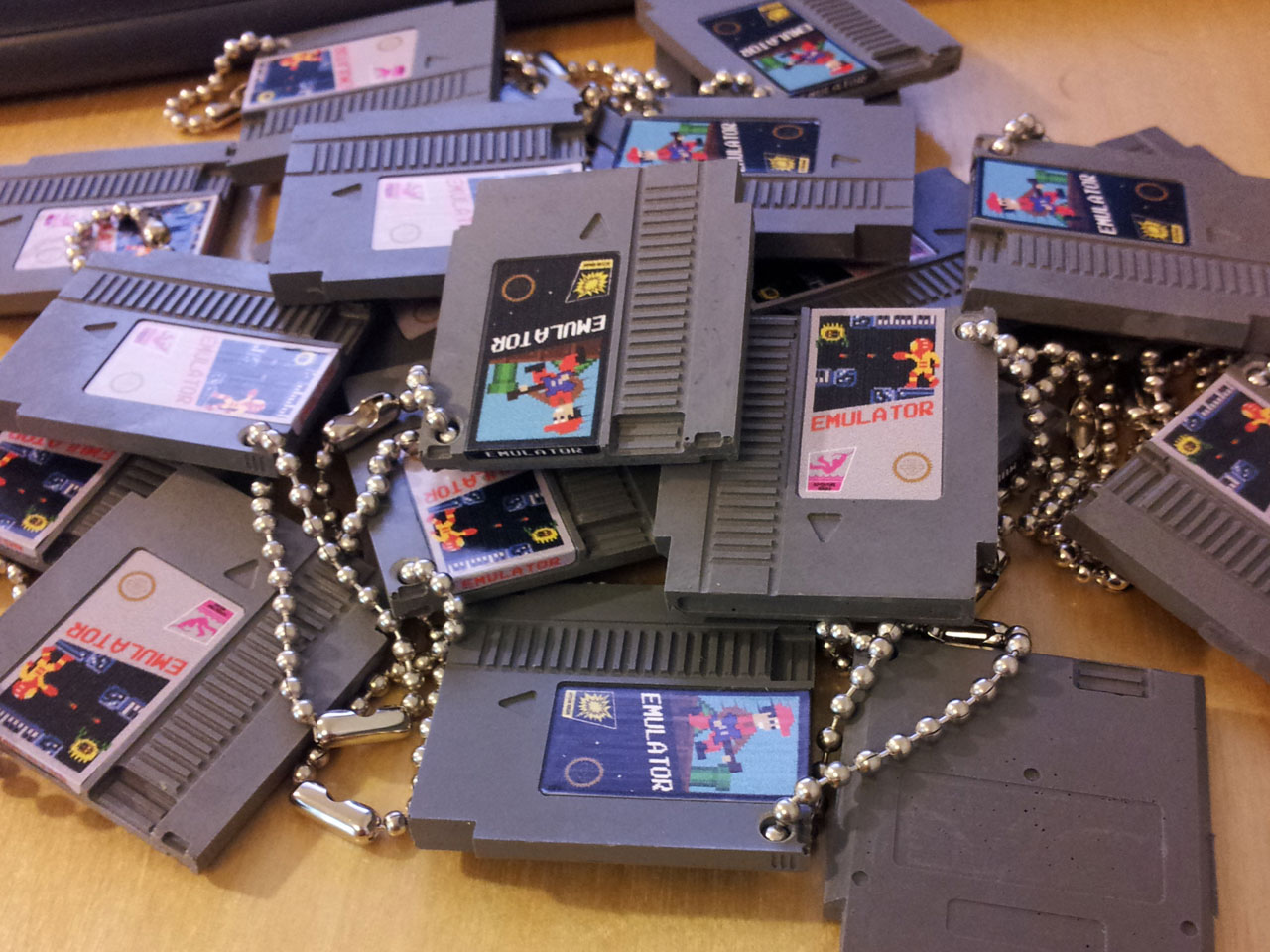
Now I just need to take them to a show and see if anybody wants to buy one..

driving an RGB LED matrix

For quite some time I've been interested in getting a good RGB matrix circuit figured out.  I've used the max7219 to do a one-bit 8x8 matrix, but the idea of being able to drive full color video is an intriguing challenge.  After a freelance job inquiry came in regarding RGB LEDs driven by an Arduino, I figured it was about time to get that all figured out. So far, I've built one circuit using a cascade of shift registers.  Three of the 8-bit registers handle each color, and one handles the common anode to do row-scanning.  An Arduino is driving the circuit by way of a hardware timer, and is continuously strobing the entire set of shift registers, turning individual colors on and off to create manual pulse width modulation.

It's working pretty well, the flicker that you see in the video isn't visible to the human eye.  However, due to the relatively low clock speed of the Arduino, only ~28 steps of brightness are possible which creates a fairly limited color space.  There's also not much head-room left on the Arduino for communication and display logic.

This circuit would be handy for a simple ambient display of some kind but I'm going to start over and try using some TLC5940's instead.  They interface via SPI and send out PWM on 10 pins with a resolution of 1024 steps which blows my current PWM resolution out of the water.  Plus, the SPI interface shouldn't be as taxing on the Arduino so I'm hopeful I can get it set up to receive and decode video at nice frame rates.

I'll post more once I have something working on my breadboard..

projecting onto mirror arrays

This March I was fortunate enough to be invited to participate in a three night event put on by Liminal as part of the March Music Moderne event in Portland.  In addition to providing projection mapping for "Capital Capitals," I worked with Bryan Markovitz to create an installation piece based on Gertrude Stein's novel "The Making of Americans." 

The installation included some custom software that I wrote which would drive projected content.  This content would be projected onto several large pieces of art hanging from the walls of the room.  This all seemed straight forward until we saw the room..  It was approximately the size of a shoe box, meaning my projector would only yield about a four foot wide image.  This gave us very little flexibility for placement of the artwork since all the projected content would end up being constrained to a very small portion of the space.  I was not happy about this.

The most obvious solution I could think of was to use a single large mirror to increase the throw distance.  After testing this idea it only added a marginal increase to the projection size, and due to the already limited space the physical setup was quite bulky. The idea of using a mirror stuck with me though.  If a single mirror works, why not use several small mirror panels, each one aimed at a different location in the room?  Thus was born the idea of an adjustable mirror array.

First I tested out the concept at home with a couple of mirrors, and once I was convinced that my projection mapping software worked through a mirror I set about building the adjustable mirror array.  The array is a set of four small (about 5" square) mirror panels mounted on brackets I made that allow the mirror to swivel horizontally or vertically.  The biggest downfall of this system is trying to drag the control points around when all the mouse movements are reversed.

The final installation included four projected regions spanning three walls of the small room with an almost 180 degree spread around the space.  Being able to project at such strange and diverse angles created a very nice effect since it removed the projector from the experience.  In most cases, it's simple to visually track back from the wall and notice the source of the projection, but when the projector is tucked over in the lower corner of the room the projected regions seem to float on the walls as if by magic.

multi-touch projection table

A few weeks ago I spent some time building an FTIR multi-touch table.  I thought I'd post some pictures to share how it turned out and mention a few of the things I learned along the way.  It's still definitely a work in progress but I wanted to document it before I forget the details.  My motivation for doing this was to have access to a large scale multi-touch interface for design and prototyping purposes.  Plus it's fun to play with and I like to build stuff.

For this screen I decided to go with the FTIR method since it's compact and I think it will allow for some interesting physical configurations that other methods, not being as self-contained, wouldn't support.  It also seemed like a reasonably simple project and had low material costs which were both important factors as this would be simply used for prototyping things in my home workshop.

Here's how it turned out:

As far as materials go, I got a chunk of 3/8" thick cast acrylic from TAP plastics, a sheet of velum, ~100 infrared LEDs, a tube of clear silicone sealant and a PlayStation 3 USB camera.  Those items along with miscellaneous wood bits and some wire were all I needed for the project.

Things I Learned

Nothing about the project was terribly difficult, but there were some stumbling points that I could have avoided if I had known a few key things.  Maybe they will help you too!

Thing 1 - Acrylic Edges

The edge finish of the acrylic makes a big difference, the clearer the better.  Rough saw cut edges scatter the IR light and will really dim the touch points.  I used varying grits of sandpaper down to about 350, then I buffed it with a polishing wheel.  You'll want to end up with an edge you can see through like glass, and should look sort of like a "hall of mirrors" effect when you peer into it edge-wise.  It's hard to take a photo of this effect, but the following picture should illustrate what I mean.

Thing 2 - Visible Light Filter

From my initial readings online I tried using a piece of the film from an old floppy disc.  This works to reduce visible light, but also blocks significant amounts of the IR which makes the touch points very dim.  I tried a piece of exposed film negative which made a dramatic difference.  There's more visible light getting through but the signal to noise ratio is really good and I'm getting excellent tracking now.

Thing 3 - Camera Position

Even though CCV has calibration for the camera, it doesn't seem to handle keystone distortion well at all.  I was unable to get good registration if the PS3 camera wasn't lined up very precisely with the screen.  I find it hard to imagine that I'm the only one who had trouble with this, maybe I'm just doing something wrong in CCV?  Anyhow, it was frustrating enough that I made my own calibration utility that sits as a shim between CCV and my own projects, correcting the TUIO coordinates on the fly.

building a bench - part 1

I've been meaning to build a bench for quite some time.  First it was going to be entirely made from maple but then TechShop imploded and I lost my access to a wood shop.  Since then the design has changed several times.  Upon enrolling in welding and metal working classes at the local community college, I changed the frame to be mostly square tube steel.

planed wood close-up

Then I realized that unless I wanted to waste a lot of money on materials while learning how to weld nice 90 degree corners, I should reconsider the frame.  The second and third design borrow heavily from an article about a reclaimed fence post bench

The second design relied on making sixteen precise bends in some flat bar stock.  Let's just say I ended up with some oddly bent flat bar and no bench legs.  The third and final design is once again going to rely on square tubing and right angles, but will require much less precision and should work just fine.

Despite the learning experiences and road blocks of the legs, the bench seat is looking great.  It's made up of seven two by fours that I bought at the Rebuilding Center.  They are old wall studs (really old.. one had a square nail in it and they actually measure 2" by 4") set on edge and laminated together with excessive amounts of wood glue and lots of clamping.

After I had a solid slab of wood I hand-planed it flat and have applied many coats of tongue oil finish.  It's silky smooth to the touch now and is looking fantastic.  For the metal work and assembly, I've taken the plunge and signed up for a full membership at ADX so I'll be doing the welding and finish work there soon.